
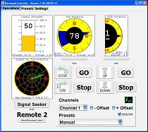
Microwave Control Operations
Detailed Operations Guide
The purpose of this document is as a follow-up to the Quick Start guide and to go into more detail into operations.
Signal Strength panel.
Pan Position panel.
Pan Button controls.
Tilt Position panel.
Tilt Button controls.
Signal Seeker operation.
Channel & Offset controls.
Heartbeat indicator.
Preset operation.
1. Signal Strength Panel. The Signal Strength panel shows the relative strength of the microwave signal coming into the receiver. The Signal Strength range is programmable. Our system is setup so that the voltage returned by the receiver at background radiation is where we put zero. In setting up the Signal Strength parameters, you can connect a voltmeter to the outputs of the receiver or you can simply turn on debug Mode and view the voltage read by the Opto22 Ethernet Brain directly. Of course, the higher the Signal Strength, the better the signal and picture you are going to get.
 |
|
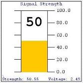 |
| Signal Strength showing a good signal. | Toggle Checkbox for Debug Mode. | Signal Strength showing current Voltage in Debug Mode. |
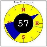
2. Pan Position Panel. The Pan position panel shows the direction our microwave antenna is pointing graphically and by showing the value in the middle of the dial This panel also has a mouse driven "GO" function that if you click on any direction on the panel the dashed green line will move to where you clicked. This is for the "GO" button under Pan position for quickly going to that location by just hitting the "GO" button. The Pan panel also has a Debug Mode that shows the voltage currently being received by the Opto22 Ethernet Brain, and it also shows the last mouse driven direction that was clicked on the panel.
 |
|
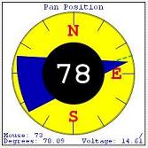 |
| Pan Position panel showing that the microwave dish is currently pointing ENE at 57°. The "GO" dashed green line appears to be pointing at about 104°. | Toggle Checkbox for Debug Mode. | Pan Position panel showing current voltage in Debug mode and the calculated direction of the microwave dish at 78°. The "GO" dashed green line according to the debug information below the dial shows at 73°. |
3. Pan Button controls. There are two indicators and four buttons in the Pan button control area.
The action indicators are the progress bar that shows activity happening to the pan heads as you can see in the screen shot below.
The "CCW" and "CW" buttons are the Counter-Clockwise and Clockwise buttons that move the dish in whatever direction you want while you hold the buttons down.
The "GO" button basically tells the dish to move to whatever position you entered into the Pan Position panel using a mouse-click.
The "Stop" button basically shuts down all movement and clears the buffer of commands to the dish. (Either "Stop" button functions in exactly the same way.)
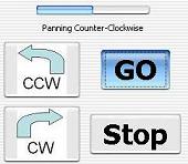 |
| Pan indicators showing movement and that the movement is in the counter-clockwise direction. |
4. Tilt Position Panel. The Tilt position panel shows the vertical direction our microwave antenna is pointing graphically and by showing the value in the middle of the dial This panel also has a mouse driven "GO" function that if you click on any direction on the panel the dashed green line will move to where you clicked. This is for the "GO" button under Tilt Position for quickly going to that position by just hitting the "GO" button. The Pan panel also has a Debug Mode that shows the voltage currently being received by the Opto22 Ethernet Brain, and it also shows the last mouse driven direction that was clicked on the panel.
5. Tilt Button controls. There are two indicators and four buttons in the Tilt button control area.
The action indicators are the progress bar that shows activity happening at the tilt head.
The "UP" and "DOWN" buttons move the dish in whatever direction you want while you hold the buttons down.
The "GO" button basically tells the dish to move to whatever position you entered into the Pan Position panel using a mouse-click.
The "Stop" button basically shuts down all movement and clears the buffer of commands to the dish. (Either "Stop" button functions in exactly the same way.)
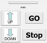 |
| Tilt indicators showing no movement. (For how it looks with movement see Pan Indicators under section 3.) |
6. Signal Seeker operation. Just press the "Signal Seeker" button and the program will move to the blocked value on the pan position and then do a 360° sweep graphing the signal strength as to position. After a full 360° sweep it then will automatically pan to the highest value.
7. Channel & Offset controls. To change the channel simply click on the "Channels" combo box and select from the options the channel you want to receive. You can also select positive or negative offsets for the selected channel by simply clicking your mouse on the appropriate offset checkbox.
8 Heartbeat Indicator. To show the health of the connection between the computer running the Microwave Control software and the Opto22 Ethernet Brain, there is a health indicator that should be constantly moving as the software continually gets updates on position and signal strength. If it seems to pause a lot, look for traffic problems on your network.
9. Preset operation.
To use a preset, simply click on the Presets combo box and select the pre-defined preset you want to use. The application will then attempt to move the pan and tilt heads into that direction.
Preset combo box:

To add presets, tune in the microwave dish to where you want to set the preset. Then change to the "Presets" tab and either add to a blank field or overwrite an existing field the name you want to associate with the preset and hit the "Save" button to write that entry. Each entry is saved separately and requires that you hit each "Save" button for each entry you change.