Microwave Control Software Configuration
After you have configured and connected up the Opto22 Ethernet Brain you are ready to configure the software.
1. The first step is to get the software talking to the Opto22 Ethernet Brain.
If you want to have the software start quickly, manually modify the mwctrl.ini file using notepad or vi and modify the following line.
configuration.ipaddress=10.80.11.40
This is the IP Address of the Ethernet Brain you will be communicating over the network. You can also modify this address in the program, but because the program relies so much on communication with the Ethernet Brain it will take a long time to start. And even then after modifying the address you will still need to stop and restart the program to get communications working.
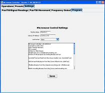
After starting up the program, click on the "Settings" tab and then the sub-tab "Program". Here you can change the Look and Feel of the Application (Aqua being the default), the IP Address of the Opto22 and the name of the microwave dish you are controlling.
2. Next get the software configured to get good readings from the pan/tilt heads and the signal strength indicator.
Next click on the "Pan/Tilt/Signal Strength Readings" sub-tab. Here we tell the program the Slot and Reference for the analog inputs that connect to the Pan/Tilt voltage inputs, and the signal strength voltage input. The slots are number 0 through 8 starting from the left to the right in the picture below. The first module is the 0-250VRMS unit that reads the voltage off the pan and tilt heads. The first module has two inputs (0 and 1). The tilt input is fed into reference 0, and the pan input is fed into reference 1. The high and low values and voltages are the upper and lower limits of the equipment. The pan should always be 0-360. (If you wanted to work in grads instead of degrees, by all means go ahead.) The tilt high value should be 90, but it can be lower as dictated by your equipment. The tilt low value can go to a minimum of -90, but how far it goes depends on your equipment (ours only goes to -14). The signal strength is basically whatever output comes out of the receiver. I setup ours to have the low value of 0 and a high value of 100.
The high and low voltages correspond to the high and low values entered in. For the signal strength I set the low voltage to the background noise level when nothing is pointing our way, and the high value to when we have a microwave truck in the parking lot pointing to the dish at full power.
A tool you have to figure out the voltages is the debug mode on the main screen. To turn on debug mode, click on the "Debug" check box in the lower right hand corner in the "Operations" screen and you will see that voltages show up under signal strength, pan and the tilt panels. Once you can see the voltages, you can move the pan and tilt heads to get the upper and lower limits. You can also power up your microwave transmitters and get your upper and lower limits for signal strengths also. (Before I put in this feature we used a voltmeter to get the values.)
The only other setting needed for pan configuration is the pan value offset. Our low voltage is at 200, and our high value is at 199, so I set the offset to 200.
For the Signal Seeker, the "Signal Seeker Scan Timeout" field tells the Signal Strength vs. pan position how long readings are to stay on the screen. By default I set this value to 100 seconds (or 100,000 milliseconds). This value will have much to do with how fast your pan motor moves the microwave dish.
 |
 |
| Pan/Tilt/Signal Strength Readings. | Opto22 Ethernet Brain with modules showing wiring setup in rack mount drawer. |
The bottom part of the screen is the setup for the Signal Strength color indicators. You can change the values of where the colors change. The values listed are for when those colors become the color shown on the Signal Strength graph. The graph at the bottom is a visual indicator of the colors and where they start. The only color that cannot be changed is black, which is the color of any signal strength value less than the first value. To change the colors, simply click on the buttons and a color chooser panel comes up. Change the color from any of the three ways to change colors: swatches, gradients, or RGB settings and hit OK when finished. The graph will show the change immediately.
3. Next we need to setup the parameters we need to move the pan and tilt heads.
Under the "Settings" tab select the "Pan/Tilt Movement" sub-tab.
The first part is simply the slot and reference values that you need for the momentary contacts to turn the pan and tilt motors on and off.
The "Blocked Pan Value" is the pan value that the pan head cannot go through. Even if you have a pan movement that can go round and round without being blocked, you will probably want a blocked value so you don't have operators wind cables round and round ...
The "Blocked Value Range" is the area around the blocked range that the software won't even attempt to go any closer to the blocked value.
The calibration values depend on the make and model of your pan tilt head. Our pan/tilt head will pan 6° each second, and tilt 4° each second. The time values are in milliseconds (ie. 1000 mSec is the same as 1 second).
The "Preset Tries" and "Preset Percent" values work together. When the software moves the pan and tilt heads automatically it will calculate how much time is required to move to the specified position. Here is an example that should illustrate how this works:
For example if you have "Preset Tries" set to 2 and "Preset Percent" set to 90% the following would happen:
Upon hitting the "Go" button or selecting one of the pre-program presets the software calculates how much time is required to move the dish to the new position. The software calculates that it will take 20 seconds to move to the new position. The software internally works in milliseconds and then converts the 20 seconds to 20,000 milliseconds.
Then the software takes the time value and multiplies it by the "Preset Percent" value and gets 18,000 milliseconds (90% of 20,000). Then the software closes the contact that controls the movement desired and 18 seconds later turns off the contact.
Because we try 2 times (as per the "Preset Tries" value) the software then re-calculates how much time would be required to move to the new position. If all went well in the previous move the software calculates that the time to move this time is 2,000 milliseconds. We apply the "Preset Percent" value again and move for 1.8 seconds to the new position.
At this point if all went well we should be within 1 percent of the target. Reality usually does something else. In practice network traffic can delay the software turning off or on the pan and tilt heads causing under runs or over runs of where you want to go. The pan tilt heads can also contribute to this as there can be play in the potentiometer readings depending on the originating direction, temperature, wind, etc.
If you live in a perfect world where there were no delays and no waffling in the values you can set the "Preset Tries" value to 1 and the "Preset Percent" to 100% and you will hit your target the first time every time. For the rest of us, the tries and percent settings get us pretty darn close.
4. Now we need to setup the interface so we can communicate to with the microwave receiver and change the pre-programmed frequencies.
Under the "Settings" tab select the "Frequency Select" sub-tab.
 |
 |
| Frequency and Frequency Offset parameters. | Microwave receiver showing remove control cable connection. |
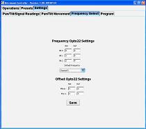
The first step is to setup the slot and reference values that will change the frequency selects in the receiver. Our equipment has 8 frequencies that can be selected by binary addition (ie. 000=0, 001=1, 010=2, 011=3, ... 111=7).
Next input the slot and reference values that will turn the plus and minus offsets on or off.
The last setup is to tell the software where you want to change the frequency when first starting the software. For example, the default frequency we use is on channel 5, so by setting the "Default Frequency" to 5, the software is instructed to automatically change the receiver to channel 5 each time the software is started up.
5. Your software is now configured for operation. Be sure to hit the "Save" button on each configuration screen to save the values of what you are working on. Changing most values will have immediate effect on the program and you will be able to see if they start working almost immediately. Changing the IP Address of the Opto22 Ethernet Brain is one of the few that requires a software restart for the parameter change to take effect.